Over Voltage Over Heat Over Current Circuit Diagram The document discusses the design basics of motor protection circuit breakers. It describes how they combine short-circuit protection and motor overload protection. The key components are a thermal overcurrent release, electromagnetic overcurrent release, and main contact system. The thermal release protects against overloads like a bimetal relay, while the electromagnetic release quickly
From a machinery design standpoint, system engineers and equipment designers must choose appropriate In the United States, there are three basic categories for circuit protective devices as they relate to this document: UL 489, UL 1077, and UL 508. As circuit breakers, they can provide motor branch circuit protection and can be used as

PDF IEEE SF Motor Protection Fundamentals Circuit Diagram
Motor Protection Circuit Breakers Motor Protection Circuit Breakers (MPCBs) combine the short-circuit and isolation functionality of a molded case circuit breaker with the motor overcurrent protection of a traditional overload relay. These devices are traditionally used in two-component starter applications, with a contactor to control a motor • Basic and advanced protection functions. • Motor Heating. • Pump Cleaning • Limp Mode • Motor Jogging and Breaking • Torque Control • 18 - 370A • Built in bypass. • User friendly HMI • Torque control. • Current limit (1.5-7*Ie) • Basic motor protection functions. • Analogue output. • Optional communication —
![10. [3] Design a protection circuit for a system that Circuit Diagram](https://media.cheggcdn.com/media/60c/60c5b7e1-f779-4629-9b3d-afdf6f940ada/phpFSLeEt)
A motor protection circuit breaker is a device designed to protect electric motors from overloads and short circuits, ensuring safe operation and preventing equipment damage. This blog will explore the functions, types, and applications of motor protection circuit breakers to provide a comprehensive understanding of their importance in various
The Complete Guide to Motor Protection Circuit Breaker Circuit Diagram
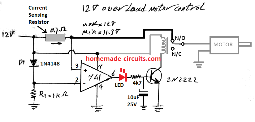
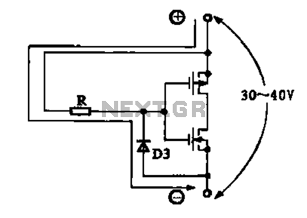
The entire circuit explanation is provided over/under cut-off voltage circuit. 2) DC Motor Over Heat Protection Module Circuit. The third problem involving temperature rise of the motor can be solved by integrating the following simple temperature indicator circuit. This circuit was also covered in one of my earlier posts.
![Solved 10. [3] Design a protection circuit for a system that Circuit Diagram](https://media.cheggcdn.com/media/c76/c76bf375-c77a-47fc-ba72-721f5310a327/phpfOoUMS)